| Vessel Diameter | 36in. (91 cm) |
| Vessel Seam to Seam Length | 10ft. (3 m) |
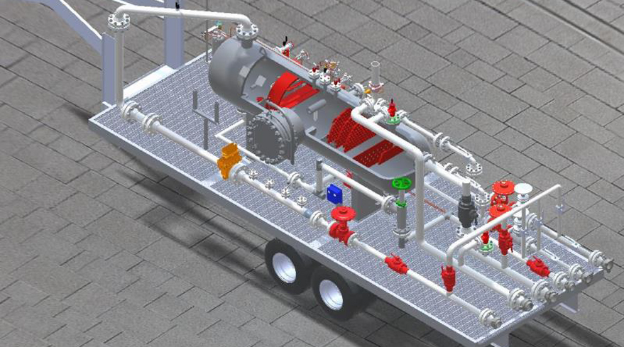
| Trailer Dimensions | 8W x 10H x 25L ft (2.4W x 3H x 7.6L m) |
| Gross Weight | 24,000 lb. (10,900Kg) |
| Working Pressure | 2,000 psi (138 bar) |
| Temperature Range | -20°F to 200°F (-29 to 93°C) |
| Gas Rate | 30 MMSCFD (850 Mm³) |
| Liquid Rate | 5,000 bbl./day (795 m³/day) |
| Pressure Safety Valve | 2 x 2" Taylor |
| Connections | |
| Inlet | 4 in. Fig 206 Female |
| Gas | 3 in. Fig 206 Male |
| Oil | 2 in. Fig 1502 Male |
| Water | 2 in. Fig 1502 Male |
| Drain | 3 in. Fig 206 Male |
| Relief | 3 in. Fig 206 Male |
| Codes and Standards | ASME Sec. VIII Div. 1, ASME B31.3 NACE MR0175, API 14.3 (AGA3), AGA 7 |
The trailer mounted horizontal three phase separators are pressure vessels used to separate and measure water, oil and gas flowing from a wellhead. In the upstream applications they are typically placed downstream of a choke manifold. The choke valve is required to drop well head pressure down to working pressure range of the three-phase separator.
In order to achieve the separation and measurement, separators are equipped with the internal and external devices. For efficient phase separations, TSI separators are designed with internal inlet diverter, vane type mist extractors, wave and foam breakers, and vortex breaker. The separator features control pilots to maintain consistent liquid level and gas pressure to optimally operate the separator. The resultant separated phases are measured by devices such as dual chamber orifice meter and turbine meters for gas and liquids respectively.
TSI separators are engineered to meet or exceed industry standards such as ASME, ANSI, and NACE. TSI separators design and fabrication are documented in each of the equipment’s data books.
Features
Benefits
Application